

This article is aimed to create and show a basic 5 channel remote control system to drive 5 lots. The input signals or the commands are sent out from a transmitter using IR transmission and obtained by the IR receiver, processed and used to drive the lots. At both the transmitter and receiver, a microcontroller is made use of to refine the signals.
Principle behind the Circuit:
The circuit works on the principle of IR communication. IR communication involves broadcasting signals making use of infrared signal as the provider. The input signal from switches is processed by the microcontroller, encoded by the encoder, regulated and sent by the transmitter. At the receiver, the modulated signal is demodulated by the IR receiver, decoded by the decoder and processed by the microcontroller to control the output lots.
5 Channel IR Remote Control Circuit Design:
The transmitter circuit consists of the three ICs � Atmel89C51 microcontroller, Encoder HT12E and timer 555.
The primary step of the layout consists of designing the microcontroller interfacing. At the input side, a 5 thing DIP button is interfaced to port P1 of the microcontroller. Another component of the input circuit layout entails developing the oscillator circuit and reset circuit. The oscillator circuit design is done by picking 2 15pF capacitors hooked up to both ends of the crystal oscillator.
The reset circuit is developed bearing in mind the required reset pulse width to be 100ms and voltage drop at reset pin to be 1.2 V. Here we pick a resistor of 10K and capacitor of 10uF to satisfy the requirements. The output side contains the HT12E encoder with its 7 address pins and the terminal allow pin linked to ground, 4 information pins attached to Port 0.
The second step of the style entails creating the timer oscillator circuit. Here we should be layout a actable multivibrator making use of 555 timer. Bearing in mind the needed oscillation frequency to be 38 KHz and thinking the value of capacitor to be 0.01 uF, we acquire the worth of Ra as 760 ohms and Rb as 1.5 K.
The receiver circuit resembles the transmitter circuit style and contains four ICs- Atmel89C51, decoder HT12D, IR receiver TSOP1738 and relay motorist ULN2004. Styling the microcontroller interfacing is same as that in the transmitter circuit, particularly the reset circuit and oscillator design.
Here, the input circuit includes the decoder and TSOP1738. The outcome pin of TSOP 1738 is linked to data input pin of the decoder IC and the 4 data result pins are attached to port P1 of the microcontroller. The address pins are based and an LED is attached to the valid transmission pin to show the transmission.
The outcome circuit contains the relay vehicle driver IC ULN2004 with 5 of its input pins hooked up to port P2 of the microcontroller and the 5 output pins hooked up to 5 relays running 5 lights.
Circuit Diagram of 5 Channel IR Remote Control System using Microcontroller:
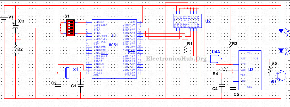
Transmitter Circuit Diagram:
Components Included in this Transmitter Circuit:
List of components and the corresponding values are shown below –
- R1 � 1M
- R2 � 10k
- R3 � 760Ohms
- R4 � 1.5K
- R5 � 100Ohms
- C1, C2 � 15pF
- C3 � 10uF
- C4 � 0.01uF
- C5 � 0.1uF
- S1 � 5 DIP switch
- V1 � 5V
- U1 � AT89C51
- U2 � HT12E
- U3 � LM555
- U4A � 7408 (AND gate)
- Q1 � BC547
How to Operate the Transmitter Circuit?
When the circuit is powered, the compiler with initialize the stack pointer and other variables and calls the main function. It scans the input pins, i.e. the signals from the switch.
In situation any one of the switches is pressed, as per the program, the compiler designates the corresponding 4 little bit worth to 4 pins of the outcome port, i.e. The needed 4 little bit output signal is produced which is supplied to the information input of the encoder.
The encoder then transforms this 4 bit identical information into serial information, i.e. produces a code for each and every parallel data input. The outcome from the encoder is attached to the reset pin of the moment 555 such that the timer will operate only when there is any type of outcome from the encoder. The timer creates a 38KHZ signal made use of to drive the IR LEDs, therefore producing a modulated 38 KHz IR signal.
Receiver Circuit Diagram:
Components Included in this Receiver Circuit:
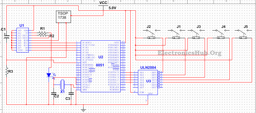
List of components and the corresponding values are shown below –
- R1 � 100Ohms
- R2 � 50K
- R3 � 10K
- C1 � 10uF
- C3, C2 � 10uF
- V1 � 5V
- U1 � HT12D
- U2 � AT89C51
- U3 � ULN2004
- Q1 � BC547
- J1, J2, J3, J4, J5
How Receiver Circuit Works?
The transmitted IR signal is received by the TSOP 1738 or the IR receiver, which demodulates the signal making use of a setup of pin diode and filter. Output from the receiver is fed to the input of the decoder which originally checks the gotten data at least three times then sends a high rhythm to the VT pin so concerning show a valid transmission. The decoder then changes the serial information input into 4 little bit identical data output. In the mean time, the microcontroller acquires started and the input pins are scanned. For a particular 4 bit input signal, the compiler designates a higher logic signal to the corresponding input pin of the relay vehicle driver. The relay driver ULN2004 is actually a Darlington variety IC which shifts the voltage degree of the obtained input signal so regarding gives a low voltage signal at the equivalent outcome pin. The relay coil linked to that outcome pin thus obtains stimulated as current circulations through it and armature steps from its initial placement so as to finish the circuit and the light starts glowing (disappointed in the picture). This procedure is exact same for turning on all various other lights.
Applications of 5 Channel IR Remote Control Circuit:
- This circuit can be used to drive number of loads like lamps.
- This circuit can be modified to drive a toy vehicle or a robot using a motor driver instead of a relay driver.